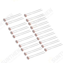
- Stock: In Stock
- Model: ST230038685
- SKU: ST230038685
>>>Manual: Contact Us<<<
Description:
This package consists of solar panels, solar charging modules, photosensitive modules, and control modules. Using the light sensing module to calculate the position of the light, adjust the steering gear to rotate the most sufficient direction of the solar panel to the light, so that the solar panel can reach the maximum power output through solar charging Charging the module to the battery. You can charge the lithium battery to provide the power required by the solar panel or DC9-24V power adapter to provide the power required for the system, and the USB 5V power supply can be input to the system to power the system. This project supports module blocking and stitching, exercise ability; procedure open source, you can understand the working principle of the module, and learn related programming ideas.
Feature:
Product Name: Solar Tracker Kit
Power input: Double -section lithium battery power supply, USB power supply
Solar board: 12V 1.92W
Appearance size: 95*180*210mm
Weight: 285g
Package includes:
(Note: battery not includes)
| Solar tracker component name | QTY. |
| UNOR3 development board | 1 |
| UNOR3 expansion board | 1 |
| Solar droplets 12V/1.92W | 1 |
| Double-sided glue 1OCM | 1 |
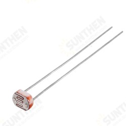
| KY-018 photosensitive resistance module | 1 |
| SG90 steering gear | 2 |
| Two female DuPont Line 3P | 4 |
| USB data cable | 1 |
| Solar tracker bracket | 1 |
| Hexagon nylon pillar M3*8 | 5 |
| Hexagon nylon pillar M3*18 | 4 |
| Hexagon nylon pillar M3*22 | 4 |
| M3*6 screw | 22 |
| M2*10 screw | 6 |
| M2 nut | 6 |
| DC005 single line | 1 |
| CN3795 Solar charging module | 1 |
| Battery box module | 1 |
| Power adapter 12V 1A | 1 |
| use 14500 lithium battery 500mAh (not includes) | 2 |
Debug method:
1. Adjust the output voltage
Connect the solar panel to the module to test the output voltage, adjust the VBAT potentiometer, reduce the clockwise clockwise, and increase counterclockwise, so that the output voltage corresponds to the full charging voltage of the lithium battery pack. If there is no output, it may be that the voltage voltage of the solar panel is lower than the MPPT setting voltage.
2. Adjust MPPT voltage
After the output voltage is adjusted, the lithium battery pack is connected. At this time, there are two methods to adjust the MPPT voltage.
The first method: One knows the best working voltage of solar panels. The best operating voltage *0.85 obtains the set voltage, measures the input voltage, and adjusts the MPPT potentiometer.
The second method: When you do n’t know the best working voltage of solar panels, you can string the multimeter current file into any pole to output the battery and adjust the MPPT potentiometer until the current is the largest.
Note: The best working voltage of solar panel temperature will be reduced. When debugging, the solar panel should be exposed to the temperature in the sun for a period of time. During debugging, the power of lithium battery should be less than 90%and cannot be 0%.
Frequently Asked Questions:
Q1. The panel always moves in a weak direction, or it is abnormal up and down, the left and right are normal or vice versa.
Answer: The position of the optical module is inconsistent with the position in the program, or the direction of the steering gear is inconsistent with the preset.
As long as the rotation direction of the steering gear is modified (180-angle) in the program, if it is 180-, it will be removed 180-, and only the angle value is retained.
Q2. The self -test is normal, and then it do not move aside
Answer: The wiring of the light -sensitive module on the left and right sides is not image by inversion. The wiring of a certain side is reversed. The order of the light -sensitive module on the right is the order of the 3 legs of upS, medium+, next-. On the left is up-, downS. Not symmetrical! Don't be in the same direction for the good -looking line.
![]()
![]()
![]()
![]()
![]()
![]()
![]()

