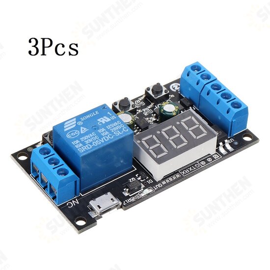
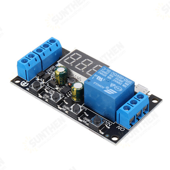
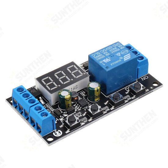
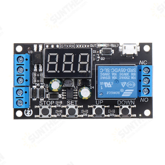
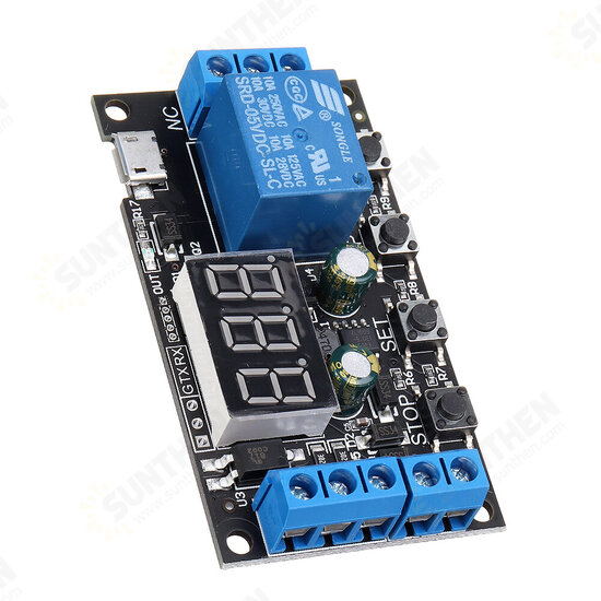
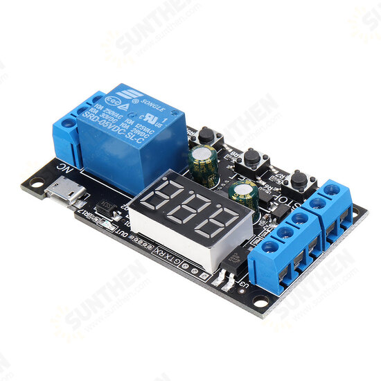
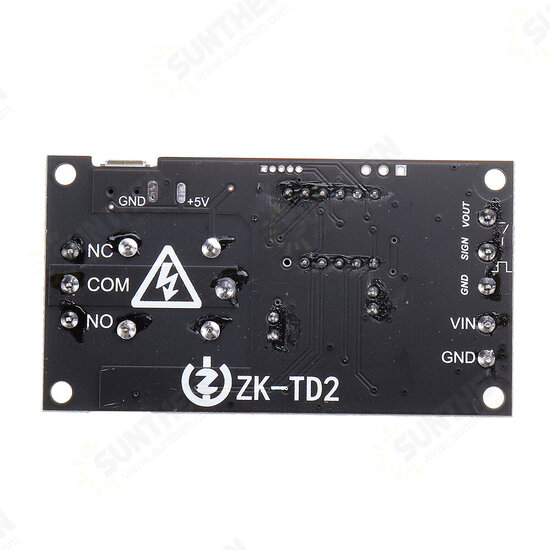
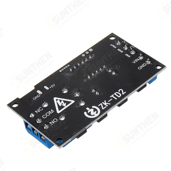
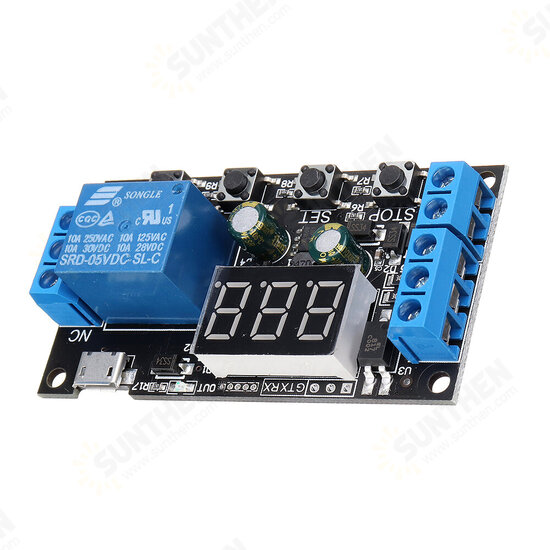


3Pcs ZK-TD2 5V 12V 24V Time Delay Relay Module Trigger Cycle Timing Industrial Anti-overshoot Timer Relay
- Stock: In Stock
- Model: ST230043183
- SKU: ST230043183
$13.99
Ex Tax: $13.99
Feature:
Wide voltage operation (5 -30V), most equipment can be used, very convenient;
The interface is clear and simple, powerful, easy to understand, and meets almost all your needs;
One key emergency stop function (STOP key), with reverse connection protection, reverse connection does not burn;
Sleep mode, after enabling, without any operation within 3 minutes, automatically turn off the display; any key to wake up;
Different OP, CL, LOP, CLL, CLH parameters can be set, these parameters are independent of each other and saved separately;
Added serial port communication function to facilitate reading and setting parameters.
All setting parameters are automatically saved after power-off.
Specification:
Working voltage: DC 5V -30V, support micro USB 5.0V power supply;
Trigger signal source:
①High level trigger (DC 3.0V~24V)
②Switch trigger
③Serial communication trigger
Output capability: can control equipment within DC 30V 5A or AC 220V 5A
Quiescent current: 20mA
Working current: 50mA
Service life: more than 100,000 times;
Working temperature: -40 -85℃;
Size: 69*38*17mm
With optocoupler isolation, enhanced anti-interference ability, industrial-grade circuit board, set parameters are always remembered after power failure.
Special attention: The relay output is a passive contact, uncharged output, which controls the on-off function of a line.
Operating mode:
Modes without triggering:
P00: After the module is energized, the relay will be de-energized CL time, and the relay will start
P01: After the module is powered on, the relay is turned on for OP time, and the relay is turned off
P02: No need to trigger the signal after power-on, the relay is on for OP time, the relay is off for CL time, the above actions are cycled; the number of cycles (LOP) can be set; the cycle ends, keep the relay off;
P03: There is no need to trigger the signal after power-on, the relay is off CL time, the relay is on OP time, and the above actions are cycled; the number of cycles (LOP) can be set; the cycle ends and the relay is kept on;
The mode that needs to be triggered:
P04: After the signal is triggered, the relay is turned on for OP time and then off; within the OP time, the signal is triggered again invalid
P05: After the signal is triggered, the relay is turned on for OP time, and then off; within the OP time, the signal is triggered again to re-timing
P06: After the signal is triggered, the relay is turned on for OP time and then turned off; within the OP time, the signal triggers reset again, the relay is turned off, and the timing stops
PO7: After the signal is triggered, the relay is disconnected for CL time, and then the relay is turned on
P08: After the signal is triggered, the relay is disconnected for CL time, and the relay is on for OP time. After the timing is completed, the relay is disconnected; another signal trigger in the cycle is invalid
P09: After the signal is triggered, the relay is disconnected for CL time, the relay is on for OP time, and the timing is completed
After that, disconnect the relay; there is a signal to trigger in the cycle, and re-timing
P10: After the signal is triggered, the relay is disconnected for CL time, and the relay is turned on for OP time, and then loop
The above action, give the signal again in the cycle, restore the initial state, stop the timing; the number of cycles (LOP) can be set; the cycle ends, keep the relay on
P11: After the signal is triggered, the relay is turned on for OP time, and the relay is turned off for CL time, and then loop
The above actions, give the signal again in the cycle, restore the initial state, stop the timing; the number of cycles (LOP) can be set; the cycle ends, keep the relay off
P12: After the signal is triggered, the relay is turned on for OP time, and the relay is turned off for CL time, and then loop
The above action, the signal is invalid again in the cycle; the number of cycles (LOP) can be set; the cycle ends, keep the relay off
P13: Signal holding function, if there is a trigger signal, the timer is cleared, and the relay remains on; when the signal disappears, the relay is disconnected after timing OP; during the timing, there is another signal, and the timer is cleared
P14: Signal hold function, if there is a trigger signal, the timer is cleared, and the relay remains disconnected; when the signal disappears, the relay is turned on after timing CL; during the timing, there is another signal and the timer is clear
P15: After the signal is triggered, the relay is disconnected for L-H time (for example, L=10, H=15, then the relay disconnection time is a random number between 10-15 seconds, L and H are set in 0.0-99.9 seconds, and H is greater than or equal to L), the relay will be turned on after the off time is over.
Timing range and how to choose
Timing range:
0.1 second (minimum) -999 minutes (maximum) continuously adjustable
How to choose the timing range:
After setting the parameter value in the mode selection interface, short press the STOP button to select the timing range; XXX. The decimal point is in the ones place, and the timing range is 1 second to 999 seconds
The decimal point of XX.X is in ten's place, timing range: 0.1 second to 99.9 second
X.X.X. decimal points are all lit, timing range: 1 minute to 999 minutes
For example, if you want to set the OP to 3.2 seconds, move the decimal point to the tens place, and the digital tube will display 03.2. Parameter description: OP on time, CL off time, LOP cycle times (1 -999 times, "---" Stands for infinite loop).
Parameters only used in P15 mode: CLL closing time random number lower limit (O-99.9) (unit S), CLH closing time random number upper limit (0-99.9) (unit S)
These parameters are independent of each other, but each mode shares these parameters. For example, the ON time OP is 5 seconds in PO1, and the user wants to switch to PO2 mode, then when entering PO2 to set the corresponding parameters, OP will also be 5 seconds;
On the main interface (display 000), short press the SET button, it will display OP (CL, LOP) and the corresponding time XXX;
If there is only OP (such as mode PO1) time in the mode, short press the SET button will only display OP and the corresponding time;
If there are OP, CL, LOP in the mode (such as mode PO2, PO3), short pressing the SET button will display OP and corresponding time, CL and corresponding time, LOP and corresponding times;
After setting the mode, you can easily view the parameters set in the current mode by short pressing the SET button on the main interface, which is very convenient!
Parameter setting method
1. First determine the working mode of the module;
2. According to the working mode of the module, in the main interface (when the module is powered on, the current working mode will flash
Operation mode (default PO1 mode), then enter the main interface, "Long press the SET button for 2 seconds and then release" to enter the mode selection interface, short press the UP and DOWN buttons to select the mode to be set (PO0~P15);
3. After selecting the mode to be set (such as PO3), short press the SET button to set the corresponding parameters, then the parameters to be set will flash (OP on time, CL off time, LOP cycle times ("---" represents unlimited) Cycle)), adjust the parameter value through UP.DOWN, support long press (rapid increase or decrease) and short press (increase or decrease by 1 unit); after setting the parameter value, short press the STOP button to select the decimal point position , Select the timing range (corresponding time 0.1 second ~ 999 minutes); short press the SET key to set the next parameter of the current mode, the process is the same as above;
4. P15 mode, after selecting the mode to be set, short press the SET button to set the corresponding parameters, then the parameters to be set will flash (lower limit of CLL disconnection time, upper limit of CLH disconnection time), adjust the parameters through UP and DOWN Value, support long press (rapid increase or decrease) and short press (increase or decrease by 1 unit), timing range (corresponding time 0.1 second ~ 99.9 seconds); short press SET key to set the next parameter of the current mode, the process is the same as above ;
5. After setting the parameters of the selected mode, press and hold the SET button for 2 seconds and then release it. The currently set mode will flash, and then return to the main interface. The parameter setting is successful, very simple!
Main interface: "000" (no decimal point) is displayed when the module is not working, and there is a decimal point when the module is working, which is very clear!
Mode selection interface: Long press the SET button to enter, after the setting is completed, long press the SET button to exit and return to the main interface, very simple!
Package Included:
3 x DC 5 -30V 1 Channel Cycle Timer Delay Relay Module


