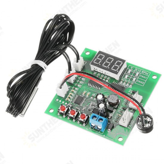
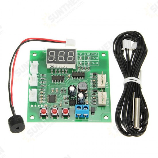
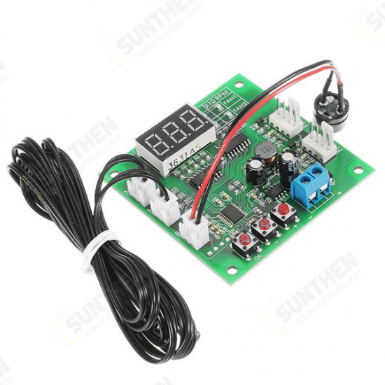


DC 12V 24V 48V 2 Way Cooling PWM 4 Wire Fan Temperature Controller Temperature Speed Display
- Stock: In Stock
- Model: ST230045720
- SKU: ST230045720
$8.99
Ex Tax: $8.99
Features:
1. DC8-60V operating voltage range (it means that the control panel can work in this voltage range; the controller power supply and fan are together in actual work; it must be powered up in accordance with fan power supply requirements, otherwise it will damage the fan).
2. Dual path independent temperature control; it take turns to display two channels’ temperature (-9.9℃to 70.1℃; error <1℃) and Fan Speed (resolution 10rpm; maximum display 999 x 10rpm; more than the speed displaying 999).
3. The low fan speed and temperature control zone are set by pressing buttons with flexible control and large setting range; program will be saved after the setting.
4. Switch stop-rotating alarm function can be set (external connecting AC buzzer keeps beeping; being shut off by default).
Performance parameters:
1. Operating voltage: DC8-60V (must be equal to fan voltage; if you use 12v fan, 24v power supply will make the fan burned)
2. Operating Current: control panel operating current 35mA (l2V) 22mA (24V)
3. Control Ability: not be limited by fan current, but fan connector pins on the board do not exceed 3A current; if using larger current fan, please connect fan power supply cable to the main power supply directly!
4. Control Output Range: 10% —l00%(this is the signal output range; the actual situation depends on fan performance)
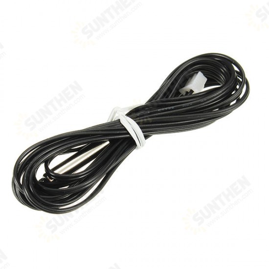
5. Temperature Probe Specifications: NTC 10K B =3950
6. Temperature Measurement: -9.9℃ to 99.9 ℃, error <2℃ (1% probe with 70℃) 3℃(>70℃)
7. Temperature Control Zone Range: accelerating speed temperature 5-94℃, full speed temperature 10-99℃
8. Speed Measurement: 10-9990 rpm, exceeding the speed displaying 999; resolution 10 rpm, display unit *10 rpm (speed measurement is based on common 2-pole signal fan design; most of the fans are 2-pole signal)
9. Stop-rotating Alarm Speed: less than 375rpm
10. Circuit dimensions: 65mm*65mm*15mm, location hole center distance 56mm*56mm, diameter 3.2mm
Wiring Connecting instructions:
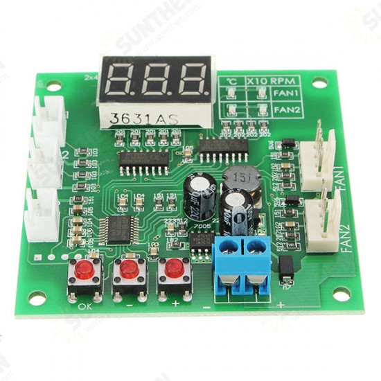
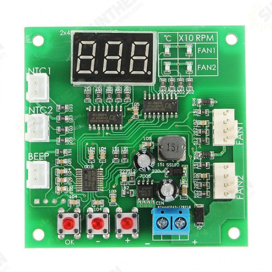
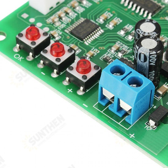
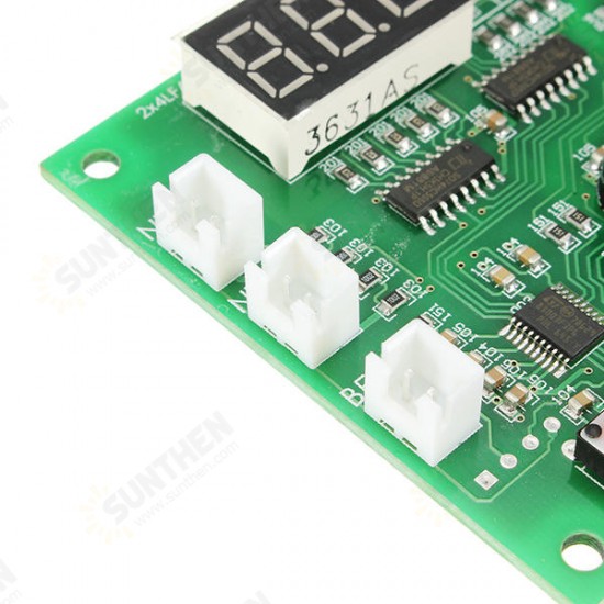
Connect blue screw connector to the main power supply (power supply voltage is equal to using fan voltage within 8-60v range); please do not connect reversely; connect “channel 1” and “channel 2” two 4P socket to the fan and power supply negative, positive, speed feedback, and PWM Control (For details, see wire connecting diagram below); connecting “thermal 1” and ”thermal 2” to NTC thermistor (parameter 10K B =3950) uses respectively two-channel fan temperature control measuring temperature; connect “beeping” connector to AC buzzer and when stop-rotating alarm is started, fan stop-rotating buzzer keeps beeping.
Wiring Connecting Note:
Single fan connector let-through current is 3A; if you need to control the higher current fan, please connect the fan power supply cable directly to the main power supply (controller controlling ability has nothing to do with fan current and please consider the power supply cable’s current let-through ability).
Display Description:
Control board display value by LED display; 4 indicating LED display on the right of the LED display meanings: line 1_two LEDs respectively stands for channel 1’s temperature and speed (x10rpm) and line 2_two LEDs respectively stands for channel 2’s temperature and speed (x10rpm). Under normal operating conditions, the four digit values will take turns to display; quickly switch digit values manually at any time by pressing the "+" "-" button; after the manual switch, it will stay under this digit value for a long time to return to taking-turns displaying. You can block 0ut the channel 2’s display according to your need.
Setting Description:
1. Basic speed settings: basic speed setting for adjusting fan speed before temperature control is started, which is the fan speed when it is lower than the accelerating speed temperature. Setting method: press the "OK" button in any operating state and at the moment, channel 1_two LEDs light up at the same time horizontally with LED display showing current setting value (10-100); set the size by pressing the “+”&“-”
button and long-press the button to do continuous modification; press “OK” button after the previous setting; enter into channel 2’s basic speed setting; using the same method to do the setting and after the setting, press “OK” button to save it and exit.
2. Temperature control zone and stop-rotating alarm settings: under normal operating state, long-press “OK” button until the display is L**(**is digit value); release the button; channel 1_two LEDs lighting up at the same time horizontally stands for being in channel 1’s accelerating speed temperature setting status; set the digit value (range 5-94, unit: centigrade) by pressing the “+”&“-”button; after the setting press “OK” button to enter into channel 1 full speed temperature status displaying “H**” ; set the amount by the same way (range 10-99, unit: centigrade); after the setting press “OK” button to enter into channel 1 stop-rotating alarm setting; “+”&“-”button setting; “boF” stands for stopping the channel stop-rotating alarm; “boN” stands for starting the channel stop-rotating alarm; after the setting press “OK” button to enter into channel 2’s digit value setting with the same quickly and setting method as the channel 1 did. After the above setting, press “OK” button to exit and save the parameters.
3. Channel 2 displays blocking setting: in control panel power-off state, keep pressing “OK” button to power up it with LED display showing “2on” (starting channel 2 display) or “2oF” (blocking channel 2 display); release “OK” button; set switch blocking by pressing “+”&“-”button; after the setting, press “OK” button again to exit and enter into the normal operating status.
4. Normal and reverse l0gic mode switch (newly added): disconnect the fan; under controller not being powered up status, at the same time press (keep pressing) “+”&“-” button to power up the controller; at the moment, controller enters into mode choosing status; release the button; press “+”&“-” button again to switch mode: displaying “F-1” is normal mode and displaying “F-2” is reverse l0gic mode; after the modification, press “OK” button to exit (automatically being saved when exiting) the setting.
Setting Note:
1. at speed and temperature zone setting state, if it stays more than 15 seconds without operation, it will automatically exit without saving any data.
2. when the temperature zone is set, the same channel full speed temperature must be higher than its acceleration speed temperature at least 5 degrees centigrade; when you set a temperature digit value not meeting this conditions, the controller will automatically adjust another temperature digit value to ensure the conditions; this is an automatic one-way adjustment and if you need to adjust back, please manually adjust another temperature digit value.
3. channel 2 blocking display settings only affect working status data display and do not affect control and parameter setting (it can work normally).
Package included:
1 x Fan temperature controller
2 x Temperature probe
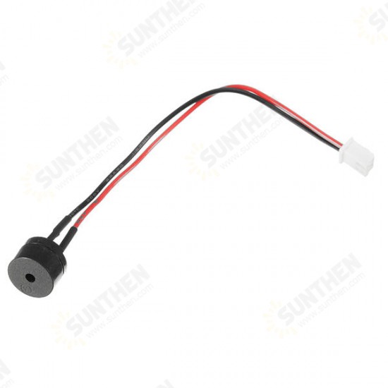
1 x Diameter 12mm length 10cm buzzer
 ,
, ,
, ,
, ,
, ,
,
1. DC8-60V operating voltage range (it means that the control panel can work in this voltage range; the controller power supply and fan are together in actual work; it must be powered up in accordance with fan power supply requirements, otherwise it will damage the fan).
2. Dual path independent temperature control; it take turns to display two channels’ temperature (-9.9℃to 70.1℃; error <1℃) and Fan Speed (resolution 10rpm; maximum display 999 x 10rpm; more than the speed displaying 999).
3. The low fan speed and temperature control zone are set by pressing buttons with flexible control and large setting range; program will be saved after the setting.
4. Switch stop-rotating alarm function can be set (external connecting AC buzzer keeps beeping; being shut off by default).
Performance parameters:
1. Operating voltage: DC8-60V (must be equal to fan voltage; if you use 12v fan, 24v power supply will make the fan burned)
2. Operating Current: control panel operating current 35mA (l2V) 22mA (24V)
3. Control Ability: not be limited by fan current, but fan connector pins on the board do not exceed 3A current; if using larger current fan, please connect fan power supply cable to the main power supply directly!
4. Control Output Range: 10% —l00%(this is the signal output range; the actual situation depends on fan performance)
5. Temperature Probe Specifications: NTC 10K B =3950
6. Temperature Measurement: -9.9℃ to 99.9 ℃, error <2℃ (1% probe with 70℃) 3℃(>70℃)
7. Temperature Control Zone Range: accelerating speed temperature 5-94℃, full speed temperature 10-99℃
8. Speed Measurement: 10-9990 rpm, exceeding the speed displaying 999; resolution 10 rpm, display unit *10 rpm (speed measurement is based on common 2-pole signal fan design; most of the fans are 2-pole signal)
9. Stop-rotating Alarm Speed: less than 375rpm
10. Circuit dimensions: 65mm*65mm*15mm, location hole center distance 56mm*56mm, diameter 3.2mm
Wiring Connecting instructions:
Connect blue screw connector to the main power supply (power supply voltage is equal to using fan voltage within 8-60v range); please do not connect reversely; connect “channel 1” and “channel 2” two 4P socket to the fan and power supply negative, positive, speed feedback, and PWM Control (For details, see wire connecting diagram below); connecting “thermal 1” and ”thermal 2” to NTC thermistor (parameter 10K B =3950) uses respectively two-channel fan temperature control measuring temperature; connect “beeping” connector to AC buzzer and when stop-rotating alarm is started, fan stop-rotating buzzer keeps beeping.
Wiring Connecting Note:
Single fan connector let-through current is 3A; if you need to control the higher current fan, please connect the fan power supply cable directly to the main power supply (controller controlling ability has nothing to do with fan current and please consider the power supply cable’s current let-through ability).
Display Description:
Control board display value by LED display; 4 indicating LED display on the right of the LED display meanings: line 1_two LEDs respectively stands for channel 1’s temperature and speed (x10rpm) and line 2_two LEDs respectively stands for channel 2’s temperature and speed (x10rpm). Under normal operating conditions, the four digit values will take turns to display; quickly switch digit values manually at any time by pressing the "+" "-" button; after the manual switch, it will stay under this digit value for a long time to return to taking-turns displaying. You can block 0ut the channel 2’s display according to your need.
Setting Description:
1. Basic speed settings: basic speed setting for adjusting fan speed before temperature control is started, which is the fan speed when it is lower than the accelerating speed temperature. Setting method: press the "OK" button in any operating state and at the moment, channel 1_two LEDs light up at the same time horizontally with LED display showing current setting value (10-100); set the size by pressing the “+”&“-”
button and long-press the button to do continuous modification; press “OK” button after the previous setting; enter into channel 2’s basic speed setting; using the same method to do the setting and after the setting, press “OK” button to save it and exit.
2. Temperature control zone and stop-rotating alarm settings: under normal operating state, long-press “OK” button until the display is L**(**is digit value); release the button; channel 1_two LEDs lighting up at the same time horizontally stands for being in channel 1’s accelerating speed temperature setting status; set the digit value (range 5-94, unit: centigrade) by pressing the “+”&“-”button; after the setting press “OK” button to enter into channel 1 full speed temperature status displaying “H**” ; set the amount by the same way (range 10-99, unit: centigrade); after the setting press “OK” button to enter into channel 1 stop-rotating alarm setting; “+”&“-”button setting; “boF” stands for stopping the channel stop-rotating alarm; “boN” stands for starting the channel stop-rotating alarm; after the setting press “OK” button to enter into channel 2’s digit value setting with the same quickly and setting method as the channel 1 did. After the above setting, press “OK” button to exit and save the parameters.
3. Channel 2 displays blocking setting: in control panel power-off state, keep pressing “OK” button to power up it with LED display showing “2on” (starting channel 2 display) or “2oF” (blocking channel 2 display); release “OK” button; set switch blocking by pressing “+”&“-”button; after the setting, press “OK” button again to exit and enter into the normal operating status.
4. Normal and reverse l0gic mode switch (newly added): disconnect the fan; under controller not being powered up status, at the same time press (keep pressing) “+”&“-” button to power up the controller; at the moment, controller enters into mode choosing status; release the button; press “+”&“-” button again to switch mode: displaying “F-1” is normal mode and displaying “F-2” is reverse l0gic mode; after the modification, press “OK” button to exit (automatically being saved when exiting) the setting.
Setting Note:
1. at speed and temperature zone setting state, if it stays more than 15 seconds without operation, it will automatically exit without saving any data.
2. when the temperature zone is set, the same channel full speed temperature must be higher than its acceleration speed temperature at least 5 degrees centigrade; when you set a temperature digit value not meeting this conditions, the controller will automatically adjust another temperature digit value to ensure the conditions; this is an automatic one-way adjustment and if you need to adjust back, please manually adjust another temperature digit value.
3. channel 2 blocking display settings only affect working status data display and do not affect control and parameter setting (it can work normally).
Package included:
1 x Fan temperature controller
2 x Temperature probe
1 x Diameter 12mm length 10cm buzzer
 ,
, ,
, ,
, ,
, ,
,

